The making of a Makerspace temperature logger, mainly in pictures. To see the chart of what has been recorded see http://www.swindon-makerspace.org/temperature
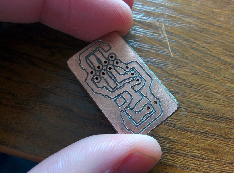
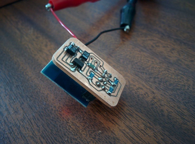
First, use the Makerspace PCB milling machine to cut a circuit board. This was the first attempt to cut a board that uses surface mount components. Really the surface mount components are on the wrong side of the board because they should be on the same side as the through hole components. This caused some odd issues with mirroring of connectors, but making double sided boards is a job for another day!
Next, soldering. Even the finest of soldering iron tips looks massive next to some of those components, so a good magnifying lamp helps. I should probably have tried to use the hot air rework station at the Makerspace. Maybe next time, either that or wait for the reflow oven project to be completed 🙂
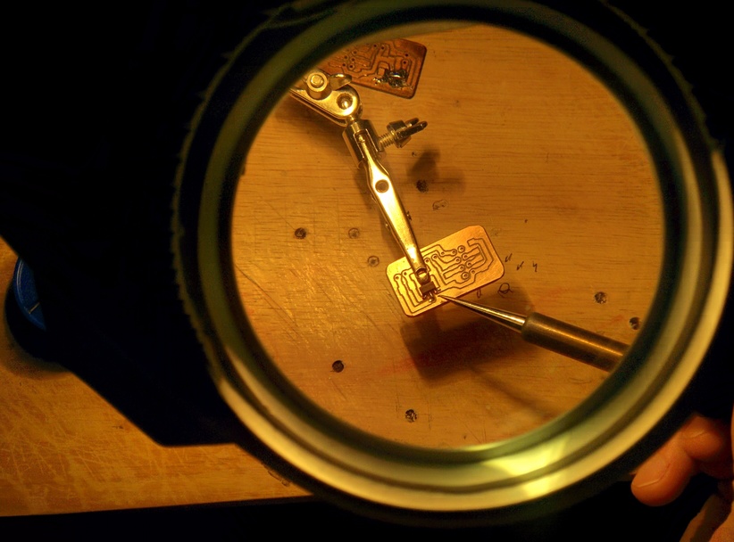
Soldering resistors and capacitors was actually a lot easier that soldering the voltage regulator. Using the crocodile clips from a pair of helping hands to hold them in place helped a lot.
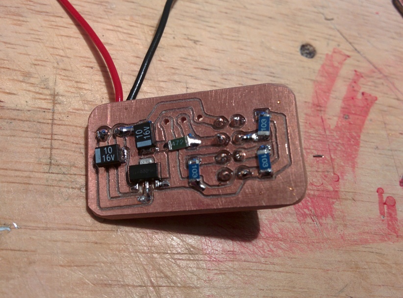
After testing the boards for shorts and checking that all the resistors were correctly soldered, an initial power-on with the ESP8266 board in place proved that everything actually worked.
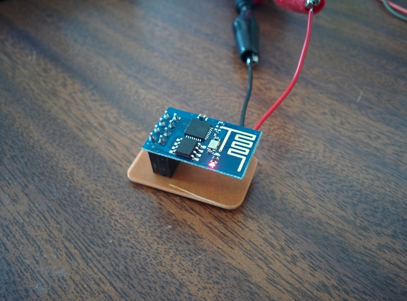
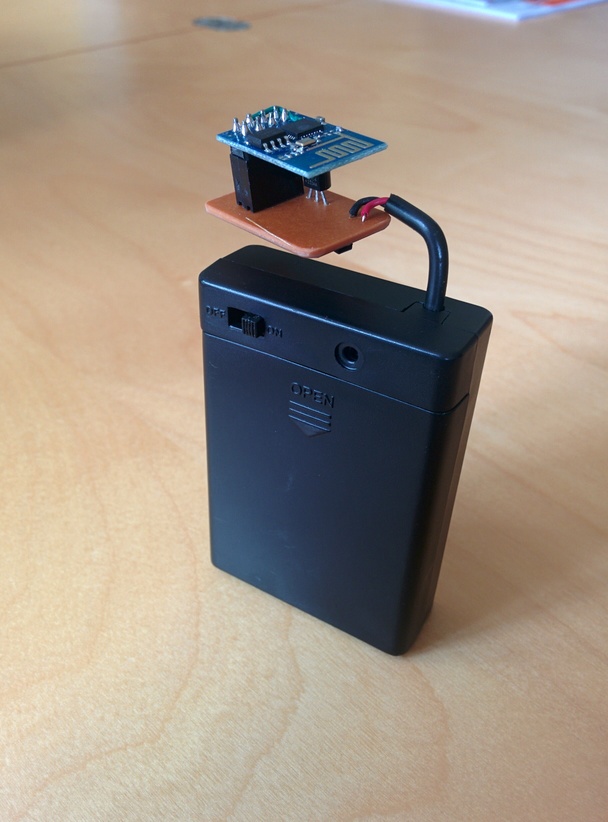
Using SMD components meant that the circuit board wasn’t all that much larger than the ESP8266 and the Dallas DS18B20 temperature sensor could fit in the space between the two boards.
Finally the red power led from the ESP8266 was removed to save a little bit of power, and the necessary additional wire from the ESP8266 chip to the reset pin was added so that deep sleep mode would work. Quite a decent result, tests with a multi-meter show it using only 28 micro amps when sleeping, which is how it spends most of it’s time.

Finally connection to a 3xAA batter holder and the project is ready to deploy. The code is written to connect to wifi, read the temperature sensor and send the data to data.sparkfun.com, then go back to sleep to conserve power.
Finally, create a 3d printed cover and place it in the space. I’ve had a variant of one of these running on a breadboard on my desk for well over a month, it only wakes up for about 4.5 seconds every 10 minutes so hopefully the batteries should last a while.
Hi,
Nice litte board. What voltage regulator and batterieis do you use?
Great to see that you also measured almost exactly the same current consumption as I did.
I noticed you connected CH_PD through a 10K resistor to Vcc. You can safely connect it directly. Saves a resistor. 🙂